Ameritron AL-1200 to GS35B Conversion
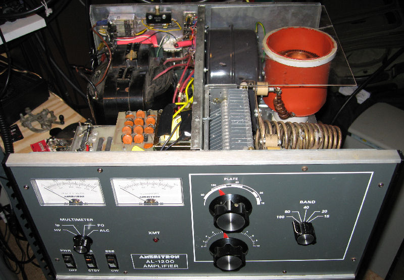
The Ameritron AL-1200 Amplifier is in current production. In its factory configuration it uses a single 3CX1200A7 (triode) tube, grounded grid configuration. Some of the nice features of this amplifier include;
- Peter Dahl transformer
- Pi-L output circuit
- Full 160m-10m coverage
- Large chassis with accessible components
Some of the ‘Russian tubes’ that have been available for the last 20 years are very reasonable in price/performance. Re-tubing of an amplifier can be a good choice (and fun too), if a tube of similar plate dissipation and operating characteristics can be found. Considerations need to be given to filament voltage, input signal feed, biasing, tube cooling and tube mounting. The output network’s impedance is really related to the operating point of the tube – the plate voltage and current (the formula for Plate Load Impedance itself is an approximation) – R(load) = Vmax / Imin. If you’re not changing the power supply, and the operating point is similar to the old tube, within the linear operating region (see the ARRL Handbook, or the old “Radio Handbook” by Orr, chapter 15) with a reasonable bias, it could be very easy to re-tube.
It’s also really helpful that others have done the a similar/identical re-tube before you.
WB8WJU and others have re-tubed the AL-1200 with a GS-35b with success; in consultation with Tom, I found out that the gs-35b is nearly a drop-in. Besides the cooling and mechanical issues, the following needed to be done:
- New 12.6v filament transformer or power supply (from DigiKey))
- mounting of a W4ZT ‘bias board’
- bias feed through an additional bias choke (per W4ZT’s suggestion)
- Re-use the existing filament chokes
Inspection
This particular AL-1200 is one of the earlier ones manufactured– # 23. The owner from whom I purchased it (Jan KX2B) was the original; the tube suffered some catastrophic failure many years ago, and the amplifier had been sitting around since.
On inspection (always a good thing to do to understand what you have), I found that the ‘slow-start’ or reduced voltage turn on resistor was open and charred (perhaps a short on startup sometime in it’s past).
Mechanical and cooling
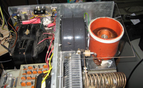
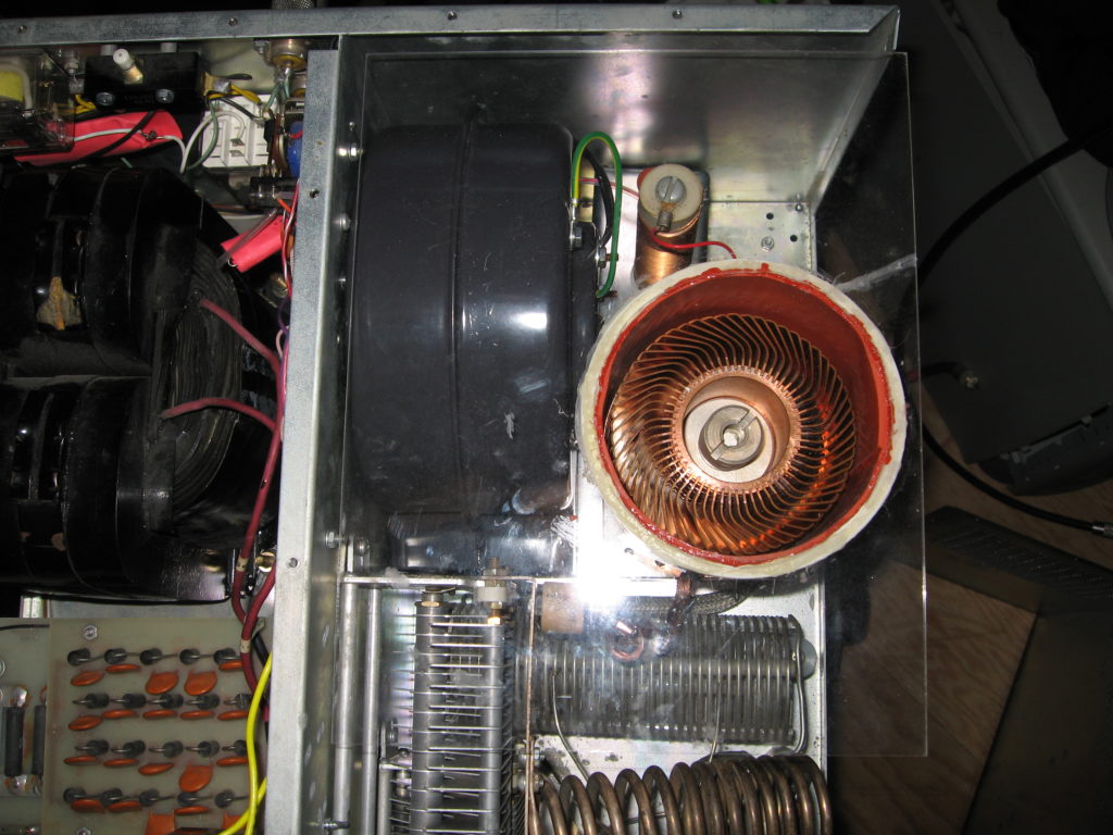
After removing all of the 3cx1200 related items, the challenge became figuring out how to ‘fit the 6lb gs35b into the 4lb box’. The original AL-1200 fan is good for 55cfm (according to Ameritron ), so that had to go, but that left even less room. Looking in the Grainger catalog, the Dayton 2C067 Blower has the motor partially set into the squirrel cage area; the CFM seems about right with about 80cfm at 0.2″ of static pressure. This seemed like the right blower, but it was too big to pressurize any kind of sub-chassis. The only orientation that worked was blowing directly towards the front panel. The challenge then became to get the air to actually blow through the tube cooler. Dividing the plate circuit area from the tube compartment was considered but discarded because of difficulty in fabrication (I don’t have a metal brake). Then an inspiration — if the existing cover’s perforations could be covered, the entire RF-side of the chassis could be pressurized! Everything then fell into place.
There still remained the means to mount the gs-35b — the original sub-chassis which held the Eimac SK-410 Socket wouldn’t fit.
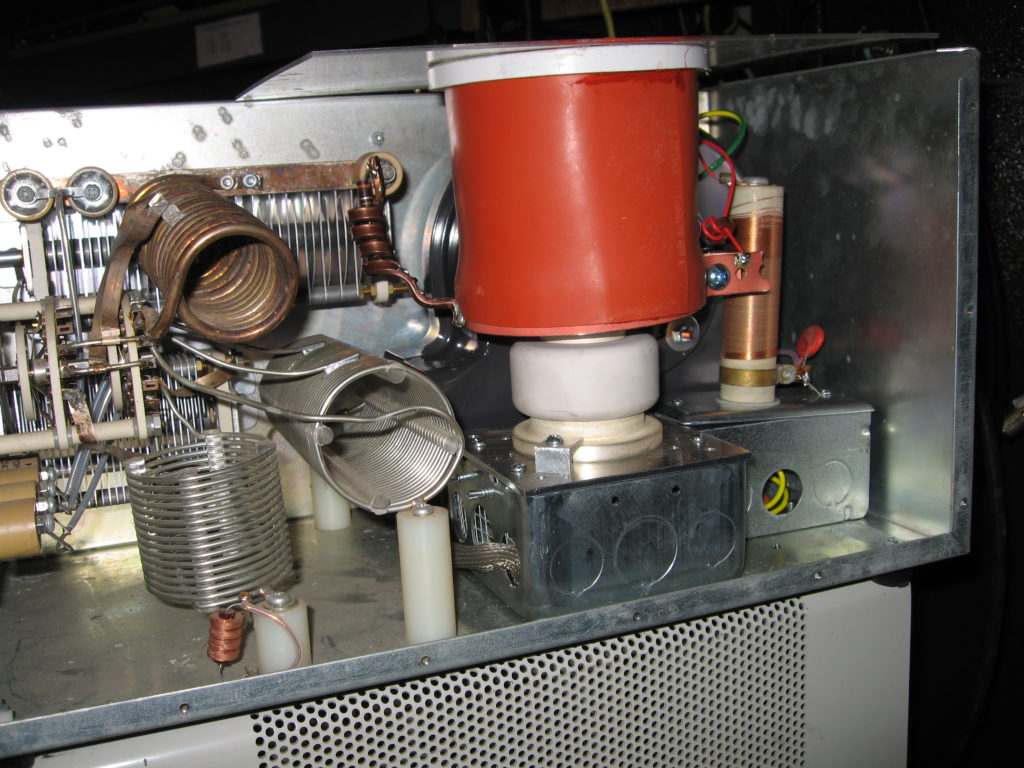
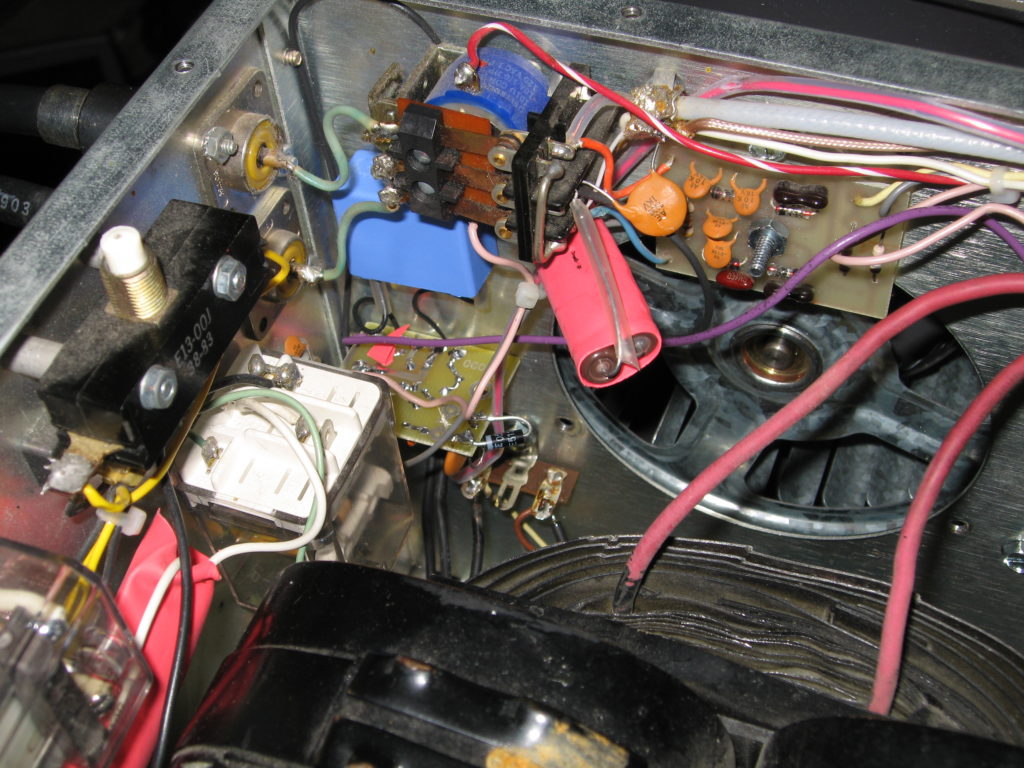
I didn’t feel like just cutting the chassis into the size I needed, since this space is important to be somewhat RF-tight — the filament chokes and cathode feed chokes are located here. It turns out that a regular 2-gang steel electrical box (Home Depot) just fits to hold a mounting plate drilled/threaded to mount the GS-35b (the mounting plate was part of WB8WJU’s gs35b socket). The original filament chokes were too long to fit inside, so they extend through one of the ‘knockouts’ to an additional single-gang electrical box. The single-gang box, with a metal cover plate, holds the plate choke.
The ventilation cover and chimney were fashioned with a ‘replacement glass’ sized 1/8″ plexiglass panel from Home Depot, a slice of a PVC tube, and some rubber sheet material left over from another project (originally obtained from McMaster – Carr). An area of plastic equal to the inside diameter of the PVC collar was cut from the plexiglass, and the PVC slice cemented on to make a small ‘collar’. The rubber sheeting material was fashioned to snugly fit the tube, and slip inside the collar, and marked with a line. The rubber material was glued up separately using Permatex high-temperature adhesive (Regular Silcone rubber adhesive (from GE and others) won’t adhere to the rubber). Then the ‘cylinder’ was inset and glued into the collar.
The tube’s filament circuit was wired in a similar way to the LK-2000 conversion — stainless steel hose clamps of appropriate diameters attach heavy-gauge teflon coated wire to the appropriate ‘ring’. I made sure that the bias was being applied to the cathode ring through the new bias choke (fabricated with wire scramble wound on a ferrite rod).
The W4ZT Bias board was modified with a 15v zener to increase the bias (gs35b’s like a high bias voltage), and installed on the rear of the chassis where the bias could be adjusted through a small hole. Note in the picture the large blue capacitor to bypass any RF making it back to the bias board.
The new filament transformer was located just ahead of the plate transformer, and above the location of the original filament transformer.
Testing and Checkout
I’m not fond of surprises when there’s over three thousand volts and high instantaneous currents involved. So, BEFORE putting in the plate transformer, I verified that the following:
- Primary resistance – make sure no shorts existed when measured from the ‘plug’
- WITH NO POWER OR PLATE TRANSFORMER CONNECTED, verified no shorts between tube anode and ground
- Verified voltage setting jumpers set for 220v
- With plate transformer removed – apply 220v via the plug, measured correct voltages on filament
- Verify control voltages were about 12v.
- I used a series resistor and 12v power supply to check that the grid-current meter was indicating correctly (apply 12v between cathode lead and ground), as well as plate current (same procedure, except put the -12v on the B- return on the power supply).
With all of those tests done, I ‘baked’ the gs35b over night with just the filament voltage (and ventilation). I like to be in the same room with a piece of equipment for it’s first few hours of operation – smells and sounds help in the diagnosis of thing that are not right.
The next day I was ready for a high-voltage checkout.
I didn’t know how long this amplifier had been since it was last powered on, so I mounted the plate transformer, and put a variac (variable voltage transformer) between it and the primary voltage. Electrolytic capacitors, if not used for long periods of time, can lose their voltage rating. Bringing them slowly up to their usual voltage can ‘reform’ the electrolytic. Being EXTREMELY careful, I set the variac to it’s minimum, and powered on the amp, and slowly (over minutes) increased the voltage to about 100vdc as measured on the HV meter setting. I left it there for about an hour, sniffing to make sure nothing was amiss (the bleeder resistors are still too cold to make any smell at that voltage). Then over a 15 minute span brought the voltage up to 300, 500, 900, 1500, then it’s maximum, 3100. Nothing unusual happened, but the bleeder resistors started to burn off whatever dust they had on them — just like turning on the furnace for the first time in a heating season.
After leaving the unit on at maximum voltage for about 15 minutes, I turned it off, removed the variac, replace the cover on the amplifier.
Setting the Bias and Testing for Operation
The no-signal plate current for the gs-35b is 100mA; I connected the output to a dummy load (just in case), but did NOT attach the rig to the input. After letting the amplifier turn on a warm up for 2 minutes, I keyed it. I adjusted the bias (using the W4ZT bias board control) through the rear panel to yield a 100mA plate current while listening for pops or trying to detect cooking component smells.
Then, I hooked up a radio, setting its output for 5 watts; I looped in a power meter between the amplifier and the dummy load, then verified the band on the amp and radio matched, and keyed down. I got about 30 watts, which I was about to touch up to 65 or 70 — the amplifier was doing it’s job.
Emboldened, I slowly brought drive up to and through 100 watts – the amplifier continued to be well behaved into the dummy load, easily yielding 1500 watts with a little more than 100 watts input.
Trying all of the other bands, the amplifier continued to be well behaved.
Operating Differences
The GS-35b requires a 90 second warm-up time; The original 3cx1200A7 doesn’t. In the pursuit of a new country, in a contest, or perhaps in the middle of the night waking up for a new one on 160m, it might be possible to forget to wait, and drive the tube before it’s ready. This can reduce the tube life or outright kill the tube by denaturing the cathode. To lessen the possibility of doing this, I built and installed a 100 second warm-up timer in series with the ‘standby’ switch; the circuit is a 555 timer driving a 2N7000 FET switching a 12v relay. The 12v keying voltage is cut-off to the keying relay until the power on delay has elapsed.
To be fancy, I replaced the often-burning-out meter lamps with white LEDs, and cemented a red LED to illuminate the grid meter during the warm up interval.
After using the amplifier for a few days encompassing the Russian DX Contest, BARTG, and the 9M4SDX operations, it’s interesting how long 100 seconds feels when you’d like to call that DX station.
Warming up — 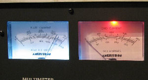
Lessons Learned – things to do differently next time
- Replace the soft-start with a different design that doesn’t destroy a power resistor over time
- Apply Plate Voltage to the tube after the warm-up period
If you have questions or comments, email me…